Project Log: Modern Vintage Computer
2021-04-22
I did not expect it to take this long to get Hello World working, but sometimes that just how things go.
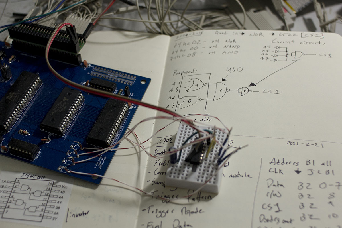
Finally work on the house is done(for now), so I was able to set my desk back up with all of my electronics equipment, and I got to work where I left off with the logic analyzer. My diode OR gate is believed to be the murder weapon, so I rummaged through the parts bin to see what I could come up with. I came up with a 74HC02 quad NOR gate chip and wired it up to test the theory
Full of fresh confidence, I powered on the board hit reset aaaand....
Nothing.
At least my tools are all setup this time, so I reconnected the logic analyzer and began digging into what was wrong. I'm fresh out of suspects so I resorted to stepping through the logic analyzer trace to see if I could find any clues. About and hour later and 104 CPU cycles I found my first clue, and learned that I'm equivalent to a 6502 running at approximately 0.0000000289 MHz.
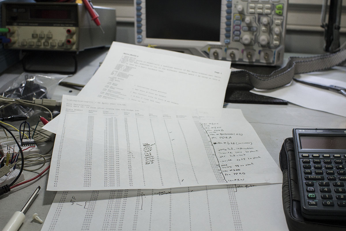
The problem is simply that when attempting to return from subroutine, bad address data is being pulled off the stack and the cpu just gets lost in a loop in wonderland. My prime suspect is now the RAM chip. I started by double checking the address translation which I have tweaked only very slightly from Ben Eater's design, but it looks right to me and it did work on the slow clock before I messed with the new OR gates for the 6522 chip. On that note, I hooked it back up to the slow clock, and now its not operating either. I don't have another RAM chip to test so I load up the parts cannon with whatever I can find on hand and fire another 6502 into the socket. I ran the computer again and encounter the same issue. This time only 77 cycles in the CPU runs into the same wonderland loop. My final idea is to see if I can test the RAM in my TL866. I know it has features to test 74 series logic.
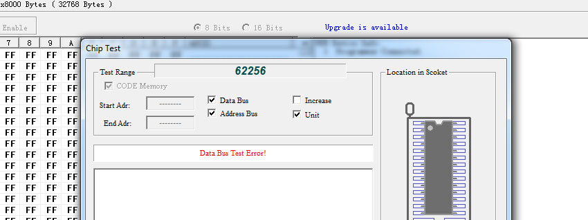
Finally I have a difinitive answer, the test immediately shows a bus error on the RAM chip, and throws errors quickly if I try and test any section of the chip individually. Time to order a new RAM chip.
It took a couple days to arrive, but I immediately installed it and it worked. Finally I can start working on writing some of my own code from scratch and adding components to the system. I would like to add a UART next I think so that I can work on some basic I/O thats a bit more "computery" than blinken lights.
2021-02-13
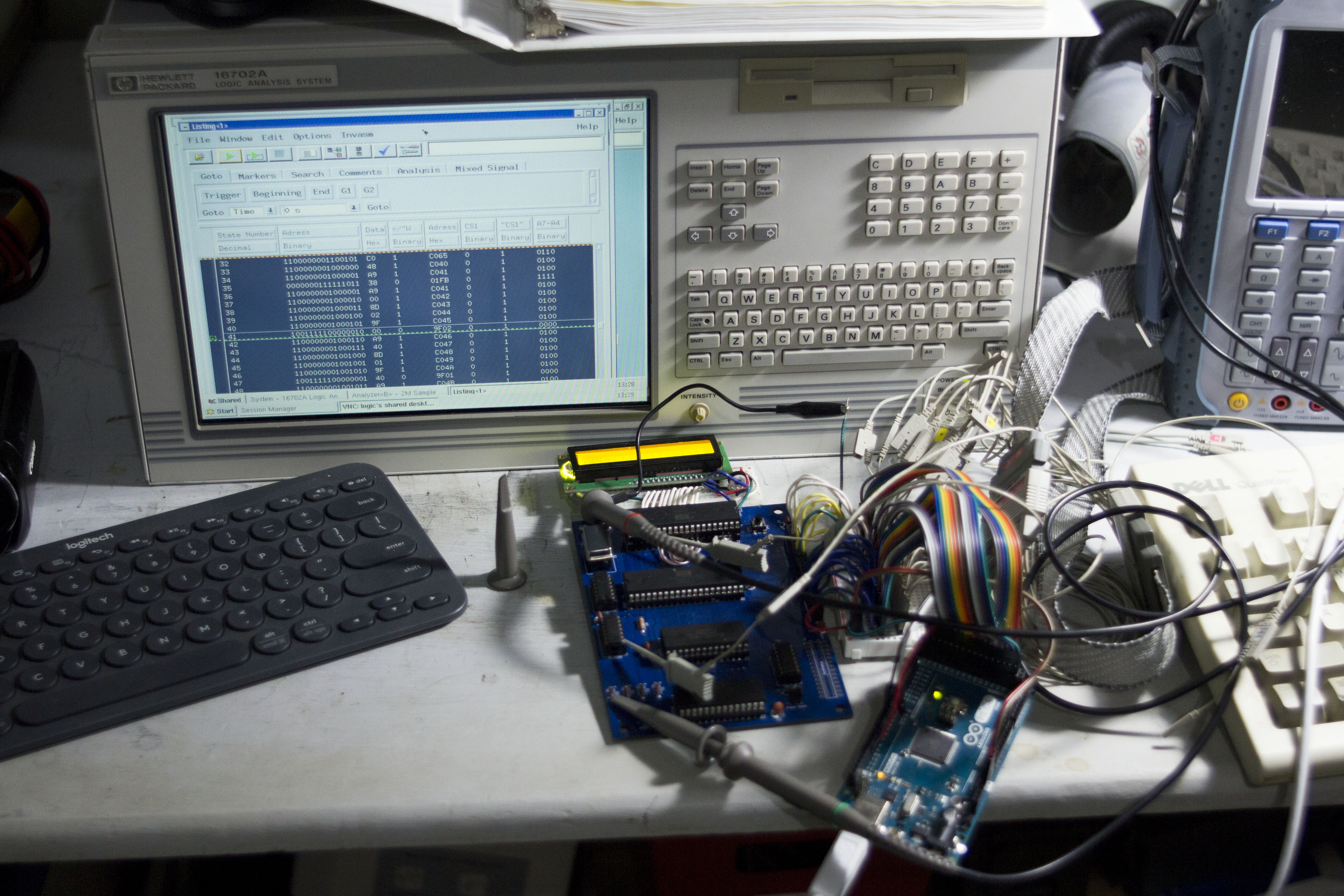
For most of the winter my electronics bench has been torn apart into boxes for some home repair/rennovation. I decided to console myself with a little auction shopping and found myself the proud new owner of an HP 16702A Logic Analysis System. It's a massively overkill logic analyzer for me as well as an intersting vintage computer running HP UX. Lucky for me, I have a problem with my circuit board I can use it to try and debug.
While I got hello world working running off my arduino monitor to generate a clock signal in the 10s of Hz, once I installed the 1MHz crystal the same code stopped working at all. The LCD didn't initialize and stayed in its freshly powered up state.
Enter the logic analyzer.
I started just checking the main address and data bus and found that the code execution quickly divereged. This would require more digging and more channels. Things rapidly got messy.
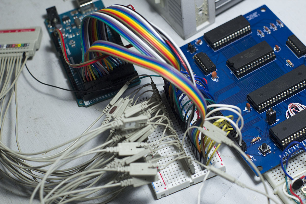
My initial suspision was on the 4 diodes I had used to create a 4 input OR gate. I thought it would be a clever way to save on another logic chip, but I didn't really do any testing to see if 1N4148 diodes used in this way would be fast enough. So I started probing the CS pins on the 6522 and the diode outputs and sure enough, when the address was supposed to translate to select the 6522, the diodes were not switching.
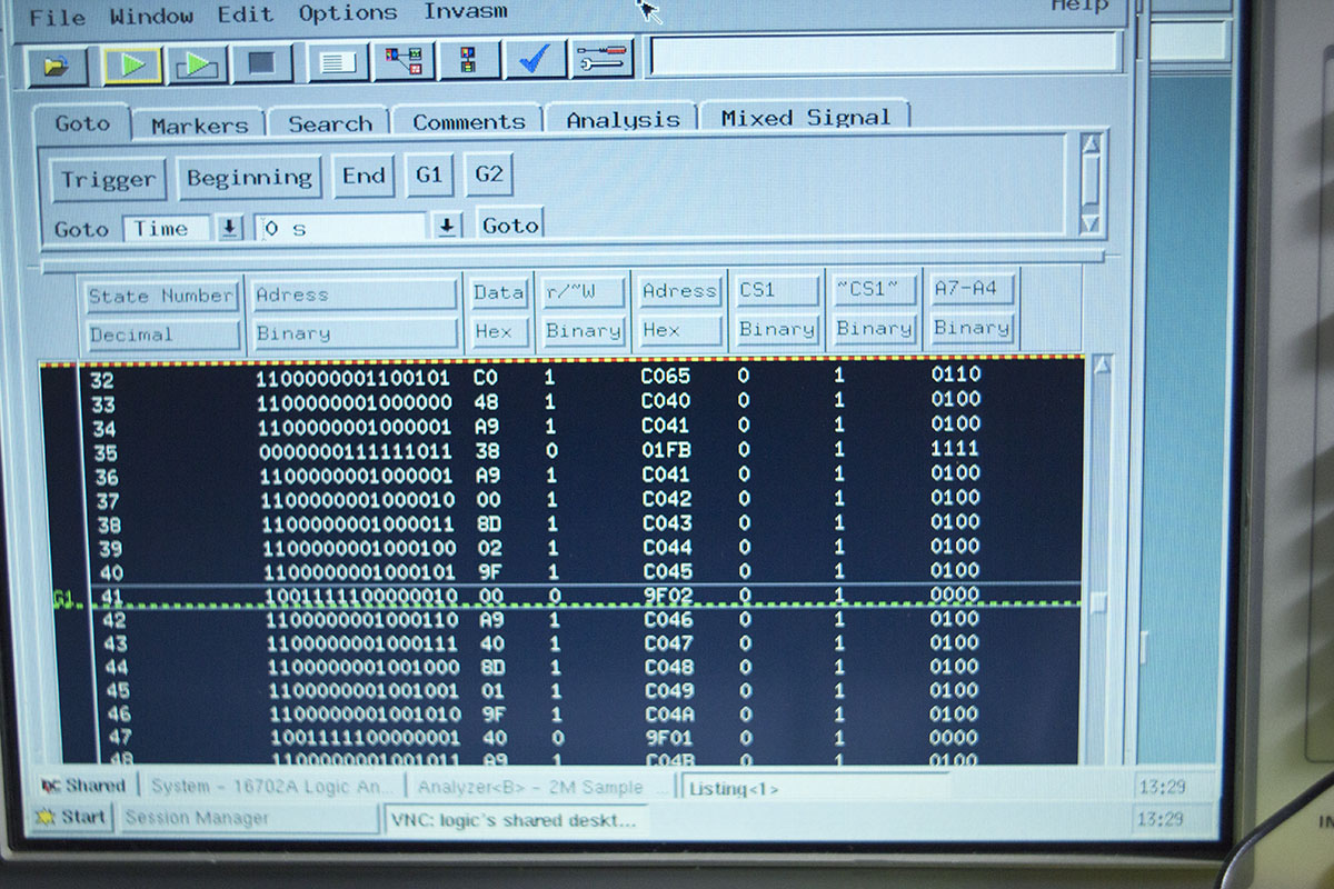
Here you can see a mere 41 cycles in, the code attempts to write to $9F02 which is the address of the DDRB register on the 6522. The chip select pin on the 6522 doesn't go high coming out of the inverter, the ~CS1~ is the input to the inverter from the diodes which stays high despite the addresses in A7-A4(the 4 ORed inputs) all going low, so I believe I have found my smoking gun. Next I will have to replace the diodes with a 7400 series logic chip, the problem may simply be that I used inappropriate diodes, but I will push on with parts on hand rather than investigating diode based options. I may investigate the diodes further when I have my MSO set back up, but at the moment catching digital and analog domain in sync isn't much of an option.
2020-11-07
Work has progressed slowly in the small chunks of time that I've been able to find. I designed a basic mainboard consisting of essentially Ben's kit with a few little tweaks to the memory map for my needs. After coming back from the fab house I spent an evening soldering in all the components and began hooking everthing up hoping for a quick repeat of my earlier hello world in the new memory space. Things didn't go quite as planned and I spent quite a while searching for issues in my code for the reason my LCD screen remained blank.
Mistake 1: I had used 2 different naming conventions for the clock signal, so they did not connect accross the board. Enter Bodge Wire #1
Hoping that was all I tried again and still a slightly different nothing happened.
Mistake 2: Somehow I reversed the data pins going into the 65C22. Enter Bodge Wire #2 and #3 and... I managed to stumble into this mistake by making it again hooking up the wires to my arduino monitor, when I started looking at the data on the bus I noticed it was all jumbled which caused me to pull out the schematic and notice my mistake.
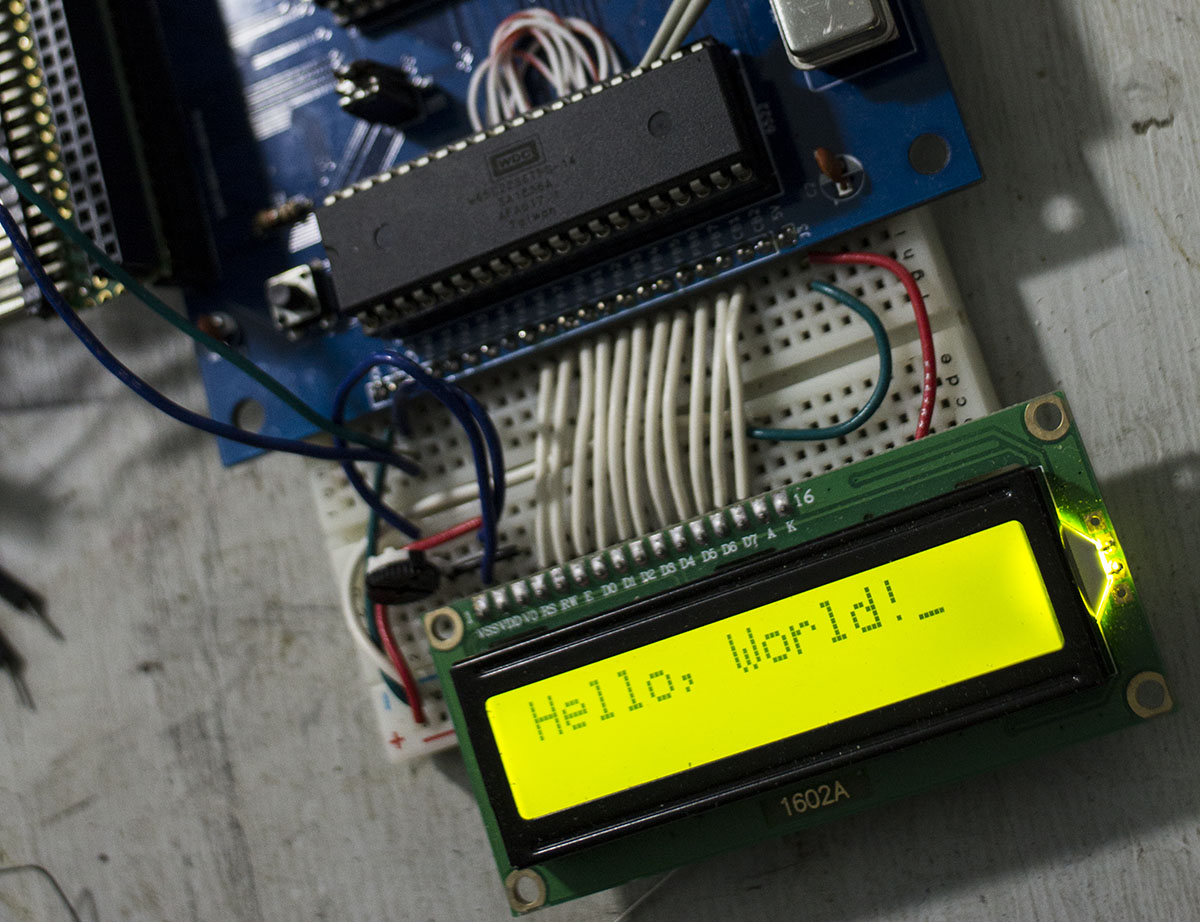
Bodge wires installed and finally Hello World works again in its new memory space.
2020-09-13
I spent some time over the weekend cleaning up the arduino monitor program. I added a couple features that I wish I had when I was debugging the basic kit. I am now able to set the monitor to run for a set number of cycles, do the same thing with a reset first, and to allow the clock to free run. I can also change the approximate speed of the clock cycle. Commands are sent over the serial port and look something like: clk 1000 which will run the clock for 1000 cycles printing data back to the serial port then waiting. I also finally got around to setting up github with the files for this project all available here.
2020-09-09
Hello World!
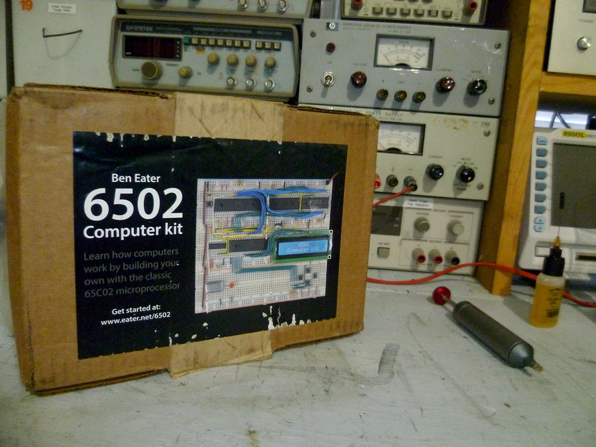
I decided to start with Ben Eater's breadboard kit. It seemed a nice easy way to get all the starting parts and make sure I had everything setup to get started. I spent most of my free time over the holiday weekend slowly wiring everything up on the breadboard, loading and running Hello World. Now that I know my build environment works I will be working on improving my tools a bit so I can focus more on the computer and less on fighting equipment.
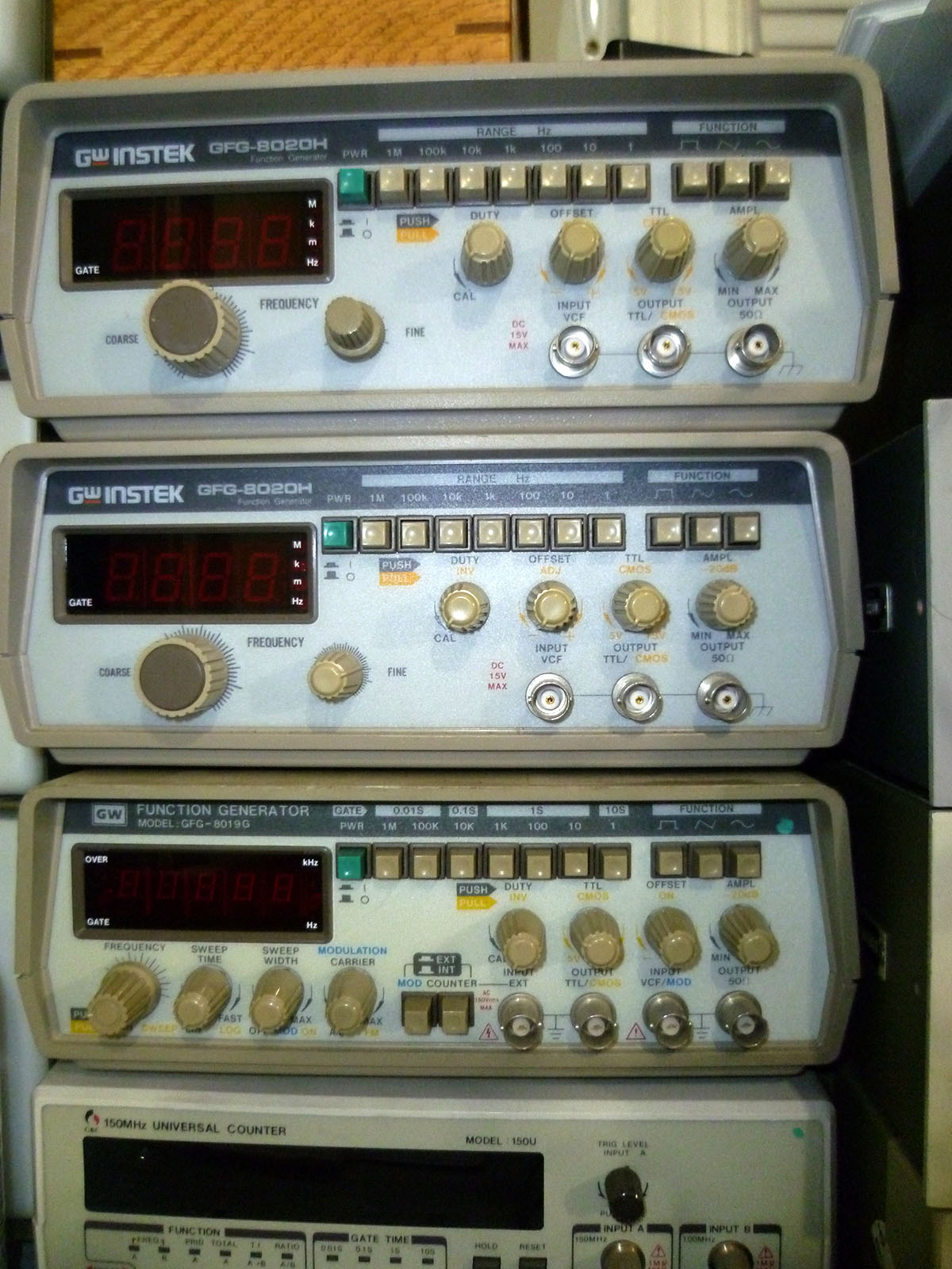
Why do you have a TTL option anyway!?
I have a couple of leftover GWInstek function generators that I thought would be perfect for this project. They have TTL level outputs and a dedicated port for it. Step 1: run TTL output to 6502 clock input, step 2: profit!
Nope.
All 3 of my function generators could not sink enough current to pull the 6502 clock pin low. I could investigate, but I won't.
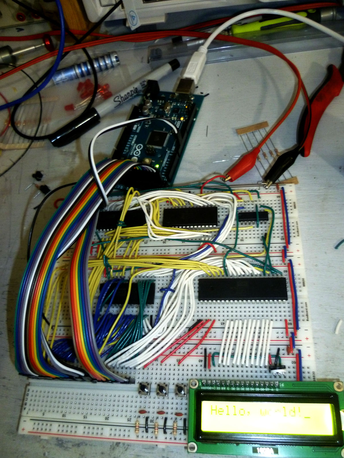
Function Generator Out--Arduino In
I probably would have been fine with adding a buffer between the function generator and the 6502, but I decided if I'm doing extra work I might as well reduce the number of tools I'm using anyway. I took Ben's Arduino Mega monitor program and decided to add a clock output function to it. Now I can send via the serial port a number and it will output that many clock cycles at about 1Hz which took quite a while to execute the Hello World program. I intend to add some more options to this monitor to make it a little more useful. The current state of the monitor is available here.
2020-09-06
Where Do I Start!?
For the past several years I've had an interest in building my own computer from scratch. Thanks to inspiration from the likes of curiousmarc, Ben Eater, Bunnie Huang, The 8--Bit Guy's Dream Computer and many of the projects at 6502.org, I've decided to actually do it. I started playing with computers in the weird crossover 16--bit to 32--bit era, and I've always been intrigued by the era of computing that came before. I often have a hard time allowing myself to work on something if I can't justify it as somehow "useful" no matter how tenuous that justification may be. This project therefore will have some justification and end goals even if they aren't that useful. My plan is to build a computer that can be useful in the electronics lab, it will be able to be programmed sitting at the computer, have some I/O to interact with the outside world and other test equipment, and be able to log/process data in some way that is useful as a standalone unit. I've been inspired most heavily by vintage 8--bit computers, but I don't want to feel too tied down to the idea of a single era so I will be moving in a more anachronistic direction.
The Ground Rules
Retro projects like this can quickly devolve into either a debate about what is or isn't vintage enough to be ok, or the challenge becomes how much can we fit into an FPGA. I don't want to get tied up too much in either of these directions so I've tried to create some ground rules/requirements to guide the project. The rules is more what you'd call guidelines than actual rules
- Learn Something
The main goal is that I enjoy getting to challenge myself to put into practice a lot of things that I think I know in theory.
- Bare Metal
I want to avoid high level languages, chips that do everything for me and system on chip type solutions. I'll be trying to learn assembly for this project, but if that becomes more trouble/less fun than hoped, I'll switch to C.
- Write All The Code
Libraries are great and all, but I want to learn how those libraries do things whenever possible I want to start from the datasheet/specs and work from there.
- Build All The Hardware
I want to avoid buying modules, boards, whole solutions that will do it all and all you need to do is sign a check. I intend to prototype on breadboards before eventually building circuit boards into system.
- Off The Shelf Parts
I've taken a lot of inspiration from people who have shared their projects and particularly ones created with an eye toward duplication. I therefore want anyone who has been inspired by this project to be able to recreate it and not be stuck by unavailable parts. I also have a bad habit of putting voltage where it doesn't belong and killing things so easy replacement parts are nice
Selecting a CPU
I originally wanted to go with something a little more modern and capable than the 6502. I started looking at the RiSCV architecture and while the ISA is open the actual silicone available at the moment seemed a little more of a black box than I want. I next considered the Atmel AVR chips since I have some experience working with them, but their architecture prevents me from writing code on the device and running it from RAM or loading it from external memory unless I flash it onto the AVR's built in flash, so that's out. I haven't much enjoyed my experiences with ARM chips and anything currently available in x86 is going to be completely unbreadboardable. So that really leaves me the vintage 8--bit home computer chips like the 6502, Z80, 68k etc. Out of these options I've found the most information readily available on the 6502 and have followed a handful of projects with the processor so it seems the best direction for me to start with.
